1. Draw a brush. The terrain patches have a minimum area of 512x512 units, so drawing brushes larger than this will result in larger patches.
a) Go to the LOD Terrain menu. Select “Create from brush.” A terrain patch will appear in place of your original brush.
2. To create larger tracts of land, and to build up from a smaller set of terrain patches, you can create multiple separate terrain patches, and then connect them.
a) Create several terrain patches apart from each other. The clone key works with terrain patches the same as with brushes, so they can be copied quickly.
b) Select and drag one of the patches, and line up one of its sides with another patch. They should be perfectly lined up in the X-Y view, but they only need to be reasonably close in the Z plane.
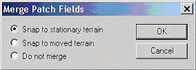
c) Release the dragged patch. If the patches are lined up within the attachment limits, you will get a small dialog:
1. Individual Patch Selection: CTRL-SHIFT-Left Click to select one 512x512 patch
2. Multiple Patch Selection: Same as #1, repeat as required
3. Full Mesh Selection: SHIFT-Left Click to select a whole connected mesh
4. Vertex Mode: Select some terrain, press V to go to vertex mode
5. Vertex Selection: In Vertex Mode, left click any vertex in 2D/3D windows
6. Multiple Vertices: Drag over vertices in 2D, or CTRL-Left Click vertices
7. Facet Selection: CTRL-SHIFT-Left click faces when in Facet Mode
To disconnect terrain patches from a larger mesh of patches, select the individual patches you want to remove, and press SHIFT-X to separate the patches from the larger mesh. You can now delete the separated patches, or move them somewhere else and reattach them to another continuous mesh.
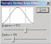
1. To raise and lower the terrain over an area, the Area Filter is used. Press SHIFT-A to access the Area Filter dialog:
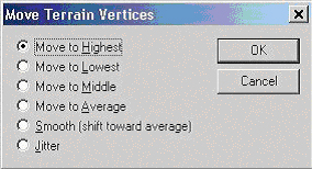
1. The vertex manipulation options are in the Move Terrain Vertices dialog. Bring this up by selecting some terrain vertices, and then pressing SHIFT-V. You must have some terrain vertices selected to bring up this dialog:

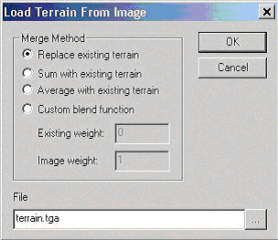
1. Terrain can also be edited by painting a grayscale image – a height field - in a paint program. The editor will export and import such images, and apply that information to any terrain in the level.
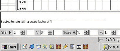
2. To export existing terrain to a height field, terrain must first be selected. Go to the LOD Terrain menu and select “Save to Image.” Enter a filename and save the .TGA file. When this is done, a message will be printed in the editor console window, indicating the scale to which the image should be imported later on:
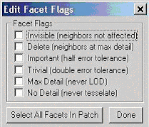
1. Facet Manipulation is essential both for aesthetics and for reduced polygon counts. It provides direct control over the way any part of the terrain shifts through different levels of detail (LOD.)
2. Press SHIFT-F to bring up the Edit Facet Flags dialog:
1. LOD Terrain menu: Scale 1 through 4 reduces the number of triangles displayed in the editor, not in the game.
2. CTRL-R will toggle the display of any terrain on/off.
3. LOD Terrain menu: Shade will display the terrain as Gouraud-shaded
4. CTRL-SHIFT-left/right square brackets ([, ]) will limit the distance to which the terrain is drawn when the Terrain Cubic Clip (restricts how much terrain is shown in the editor to enhance performance) button is active:

1. The maximum allowable vertical elevation change between any vertices within a 512x512 terrain patch is just under 512 units.
2. Terrain can only be formed initially on the X-Y plane.
3. Any facet options such as Delete, which affect neighboring facets’ LOD severity, will also influence the LOD of facets further out; there is a minor propagation effect that takes place due to the LOD system. It takes some distance to go from a max detail (many small triangles) portion of terrain to back to normal or to low detail (larger triangles.)
4. The facet flag for “Max LOD” makes the affected triangles draw at ter_maxlod = 6, which is the maximum setting. Even though the game defaults to ter_maxlod = 4, these affected triangles will go all the way to ter_maxlod = 6.
5. The editor does not interpret and display facets as they are rendered in the actual game. (ie: LOD effects are not shown in the editor.)
6. Terrain patches do not block VIS.
7. The terrain system also has a max triangle count. If the map has no vis data this defaults to 32768; with vis it defaults to 8192. You can change this with ter_maxtris and a ter_restart (see Console Commands below.)
ter_minlod: minimum LOD in the pre-tesselation stage, 0 - 6 (6 = max tesselation) -- requires ter_restart
ter_maxlod: maximum LOD in the dynamic tesselation. Precalculated tesselation may exceed this.
ter_maxtris: (integer) maximum triangles in the scene. The terrain system will not draw more triangles than this. Requires ter_restart.
ter_restart: recalculates the base LOD, and adjusts the maxtris. Automatically happens with a vid_restart.
ter_crater: creates a crater in the terrain, part of testing a deformable terrain system
ter_count: (0/1) r_speeds for terrain
ter_geomorph: (0/1) deactivates the LOD system – all terrain is drawn at full detail
ter_error: (0 to 10.0, 10.0 default) adjusts how aggressively the LOD system reduces terrain detail, ranges from 0 to 10.0. Less error = more detail sooner.
ter_lock: (0/1) locks display of terrain, to show effects of view frustrum culling (any terrain not visible to the engine from the current viewpoint is removed to improve polygon counts)
ter_cull: (0/1) disables the view frustrum culling; all terrain is drawn regardless of visibility